Description
- These step-by-step instructions will guide you through fitting fibers’ orientation data in 2D space (on a plane)
-
Fiber is an important structure of cardiac muscle which plays a critical role in cardiac muscle properties.
Therefore, the heart model will be realistic if it has fiber data. - The concept of fiber fitting is to put the initial value of fiber angle (in radian) which should specifically refer from Xi(1) or Xi(2) direction
-
An automated script that runs this tutorial is included in the Continuity installation: \examples\data02\cubic_fib_fitting.py. To run it, click File→Read script→Python or session script
Start Continuity
- Launch the Continuity Client
-
On the About Continuity startup screen
-
check the fitting box under Use Modules:
-
-
Click OK to bring up the main window
Set up mesh
-
-
Select rectangular cartesian in the Global Coordinates: pop-up menu
-
Click OK to submit Coordinate Form
-
-
-
Choose Lagrange Basis Function→2D→Linear-Linear
-
Click Add
-
Choose Hermite Basis Function→2D→Cubic-Cubic
-
Click Add
- Verify that the list of basis functions now contains:
- Linear-Linear Lagrange 3*3
- Cubic-Cubic Hermite 3*3
-
Click OK to submit Basis Form
-
-
-
Click Import/Export/Graph button to open Continuity Table Manager
-
Continuity Table Manager→File→Open…
-
Select tab-delimited nodes file ( nodes.xls )
-
-
- You should now have nodes numbered 1-25
-
Click on the Field Vector 1 tab
-
Select Cubic-Cubic under Field Variable 1
-
Click on the Fiber Angle tab
-
Select Cubic-Cubic under Fiber Angle, Transverse Angle, and Sheet Angle
-
Click OK to submit Node Form
-
-
-
Click Import/Export button to open Continuity Table Manager
-
Continuity Table Manager→File→Open…
-
Select tab-delimited elements file ( elems.xls )
-
-
- You should have 16 elements in the list
-
Click OK to submit Element Form
-
-
-
Click the lines radio button
-
Click Render
-
-
Mesh→Edit→Material Coordinates…
-
Click on the OK Button
-
-
-
Leave default settings and click OK
-
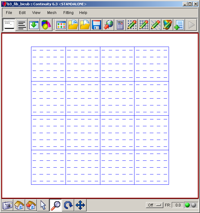
- The mesh should now look similar to the first screenshot above
Set up fitting
-
If the Fitting menu is not loaded, select File→Load Continuity Modules…
-
Select fitting and click OK
- The menu bar should now show the Fitting command
-
-
-
Click Import/Export/Graph button to open Continuity Table Manager
-
Continuity Table Manager→File→Open…
-
Select tab-delimited data file ( data.xls )
-
-
- You should now have Data numbered 11-169
-
Click OK to submit Data Form
-
-
-
Simply click OK after opening the Weights form
-
-
-
Simply click OK after opening the Constraints form
-
-
-
In the Cooridinates tab, select coord_1, coord_2, coord_3 for the three coordinates
-
In the Fibers tab, select field1_Var1 for Fiber Angle
-
In the Fitting Variables tab, *deselect* Coordinate 1, Coordinate 2, Coordinate 3, and Fiber Angle
-
Click the Fit button (Don’t close the Fit Data form yet)
-
Go back to the Fit Data form. In the Fitting Variables tab, check only the Fiber Angle checkbox
-
Click the Fit button
-
-
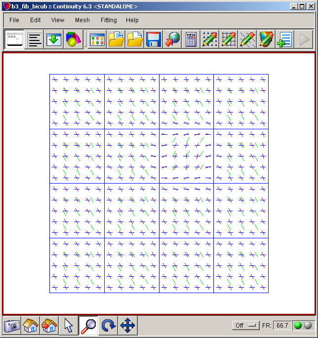
Mesh→Render→Fibers… (Note: you should render mesh fibers, not fitting fibers)
-
Leave the default values and click OK
-
-
-
Click on fiber vectors4 in the list on the left
-
Click on the Colors tab
-
Change the R,G,B color field to 1,0,0 to change the color to the brightest red
-
Click on data vectors3 in the list on the left
-
Change the R,G,B color field to 0,1,0 to change the color to the brightest green
- Click somewhere in the rendered window to refresh the image
-
- The mesh should now look similar to the second screenshot above
Pre-built model
This cont6 file contains all data and parameters for this problem: fit3.cont6

