Contents
Description
- In this example a 3-D cylindrical mesh is created in cylindrical polar coordinates using one trilinear Lagrange element.
- The nodal coordinates and element connectivities are read from tab-delimited spreadsheets.
-
An automated script that runs this tutorial is included in the Continuity installation: examples\mesh05\cylinder.py. To run it, click File→Scripts→Read script→Python or session script
Start Continuity
- Launch the Continuity Client
-
On the About Continuity startup screen
-
leave the mesh checkbox checked under Use Modules:
-
-
Click OK to bring up the main window
Create coordinates and basis function
-
-
Select cylindrical polar in the Global Coordinates: pop-up menu
-
Note that we are not using rectangular cartesian as in most other tutorials
-
Click OK to submit Coordinate Form
-
-
-
Choose Hermite Basis Function→3D→Linear-Cubic-Cubic
-
Click Add Linear-Linear-Linear
- Verify that the list of basis functions now contains:
- Linear-Cubic-Cubic Hermite 3*3*3
- Linear-Cubic Hermite 3*3
- Cubic-Cubic Hermite 3*3
- Cubic-Linear Hermite 3*3
-
Click OK to submit Basis Form
-
Read nodes and elements
-
-
Click Import/Export/Graph button to open Continuity Table Manager
-
Continuity Table Manager→File→Open…
-
Select tab-delimited nodes file (nodes.xls)
-
-
- You should now have nodes numbered 1-4
-
Click OK to submit Node Form
-
-
-
Click Import/Export/Graph button to open Continuity Table Manager
-
Continuity Table Manager→File→Open…
-
Select tab-delimited elements file (elems.xls)
-
-
- You should now have only one element in the list
-
Click OK to submit Element Form
-
Calculate and render mesh
-
-
Click the lines radio button
-
Click Render to display mesh wireframe
-
-
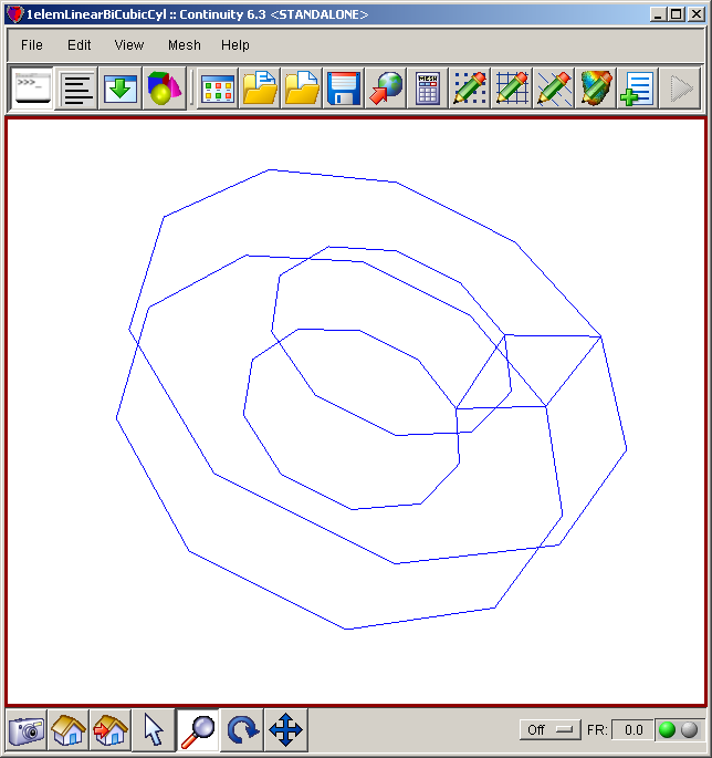
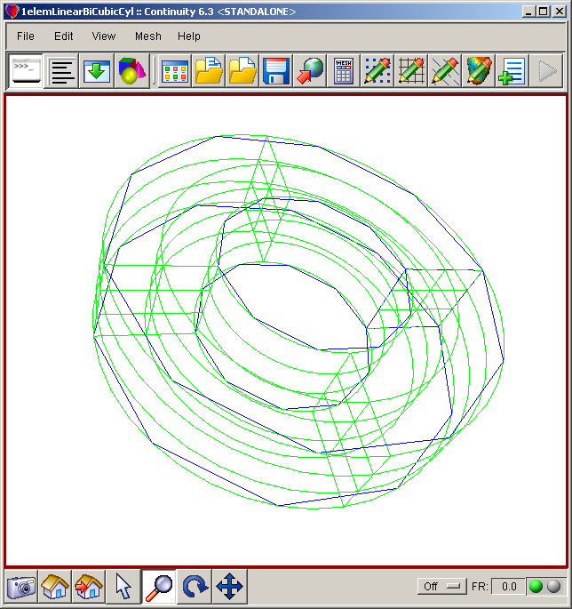
The mesh should look simliar to the first screenshot above. You may need to rotate the image to get it to appear as in the first screen shot above. The other two screen shots show meshes that can be obtained by running the script indicated at the top of the tutorial.
Pre-built model
This cont6 file contains all data and parameters for this problem: mesh5.cont6


