Contents
Description
- In this example a 3-D spheroidal mesh is created in spherical polar coordinates using one trilinear Lagrange element.
- The nodal coordinates and element connectivities are read from tab-delimited spreadsheets.
-
An automated script that runs this tutorial is included in the Continuity installation: examples\mesh12\sphericalPolar.py. To run it, click File→Scripts→Read script→Python or session script. Note that you may not be able to see through the large outer sphere; however, you can temporarily hide that sphere from View→Show Open Mesh→element surfaces4→Properties tab→ click/unclick the Show/Hide button.
Start Continuity
- Launch the Continuity Client
-
On the About Continuity startup screen
-
leave the mesh checkbox checked under Use Modules:
-
-
Click OK to bring up the main window
Create coordinates and basis function
-
-
Select spherical polar in the Global Coordinates: pop-up menu
-
Click OK to submit Coordinate Form
-
-
-
Choose Lagrange Basis Function→3D→Linear-Linear-Linear
-
Click Add Linear-Linear-Linear
- Verify that the list of basis functions now contains:
- Linear-Linear-Linear Lagrange 3*3*3
- Linear-Linear Lagrange 3*3
-
Click OK to submit Basis Form
-
Read nodes and elements
-
-
Click Import/Export/Graph button to open Continuity Table Manager
-
Continuity Table Manager→File→Open…
-
Select tab-delimited nodes file (nodes.xls)
-
-
- You should now have nodes numbered 1-4
-
Click OK to submit Node Form
-
-
-
Click Import/Export/Graph button to open Continuity Table Manager
-
Continuity Table Manager→File→Open…
-
Select tab-delimited elements file (elems.xls)
-
-
-
Click OK to submit Element Form
-
Calculate and render mesh
-
-
-
Click on nodes1 in the list on the left
-
Click on the Properties tab
-
Change the Size field to 0.1 and hit Enter to make the nodes a little bit bigger
-
-
-
-
Click lines radio button
-
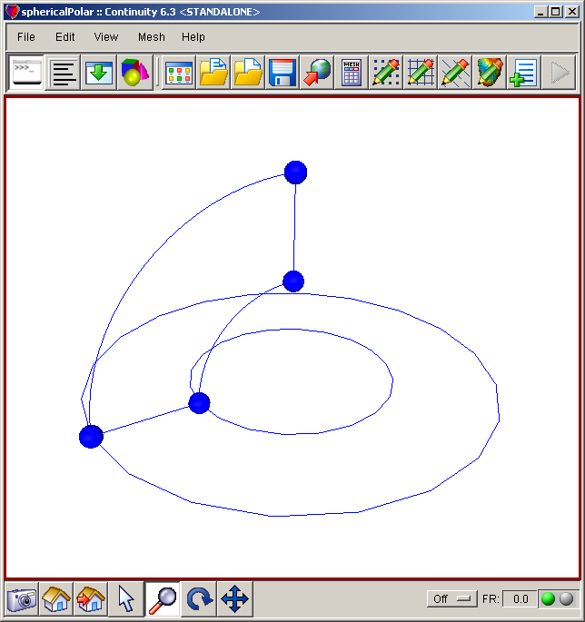
Click Render to display mesh wireframe
- The mesh should now look similar to the first screenshot, you might have to rotate the mesh to get the same view.
-
-
-
Click surfaces radio button
-
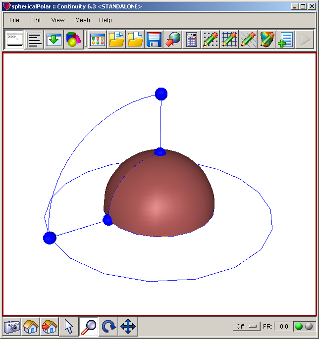
Click Render to display mesh surfaces
- The mesh should now look similar to the second screenshot.
-
-
-
Click surfaces radio button
-
Enter 1.0 for the Location field
-
Click Render to display mesh surfaces
-
-
Click on element surfaces4 in the list on the left
-
Click on the Properties tab
-
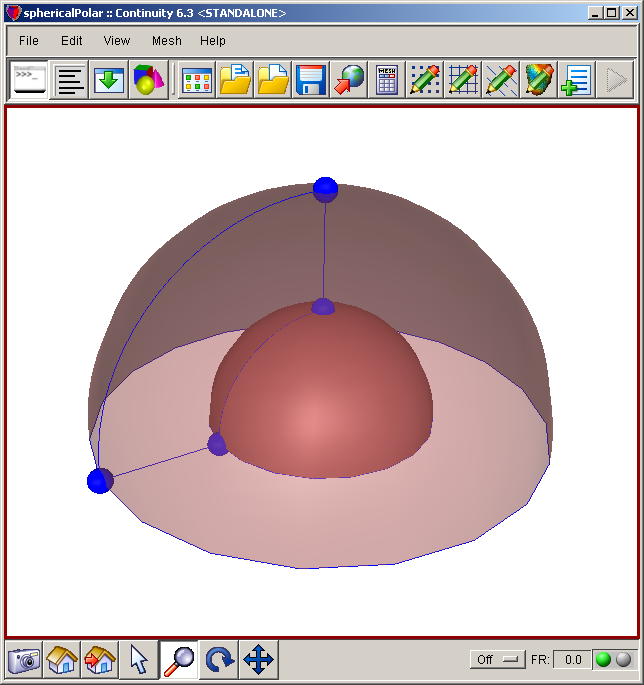
Drag the Opacity scale bar under to 50
-
- The mesh should now look similar to the third screenshot.
-
Pre-built model
This cont6 file contains all data and parameters for this problem: mesh6.cont6
-
Warning: Render Fields does not always work correctly with the DejaVu renderer on laptops. If this is the case, try using the OpenMesh renderer.


