Contents
- Create a Prolate Spheroidal Mesh and Convert to Cartesian Coordinates
- Description
- Start Continuity
- Create coordinates and basis functions
- Read prolate spheroidal nodal coordinates and element
- Calculate and render mesh
- Refine mesh circumferentially into four elements
- Change basis functions to cubic Hermite and render mesh
- Convert coordinates to rectangular Cartesian
- Pre-built model
Description
- In this example, a 3-D ellipsoidal mesh is created in prolate spheroidal coordinates using one trilinear Lagrange element. It is then converted to a 4-element cubic Hermite mesh in Cartesian coordinates.
- The nodal coordinates and element connectivities are read from tab-delimited spreadsheets.
-
The steps below are saved in a script that can be found in the examples directory on your Continuity client .../continuity/pcty/examples/mesh04/convertToCartesianUnit.py which can be executed automatically with File→Scripts→Read Script→Python script
Start Continuity
- Launch the Continuity Client
-
On the About Continuity startup screen
-
leave the mesh checkbox checked under Use Modules:
-
-
Click OK to bring up the main window
Create coordinates and basis functions
-
-
Select prolate spheriodal in the Global Coordinates: pop-up menu
-
Enter 3.75 in the Focus Position field
-
Click OK to submit Coordinate Form
-
-
-
Choose Hermite Basis Function→3D→Linear-Cubic-Cubic
-
Click Add Linear-Cubic-Cubic
-
Choose Hermite Basis Function→3D→Cubic-Cubic-Cubic
-
Click Add Cubic-Cubic-Cubic
- Verify that the list of basis functions now contains:
- Linear-Cubic-Cubic Hermite 3*3*3
- Linear-Cubic Hermite 3*3
- Cubic-Cubic Hermite 3*3
- Cubic-Linear Hermite 3*3
- Cubic-Cubic-Cubic Hermite 3*3*3
-
Click OK to submit Basis Form
-
Read prolate spheroidal nodal coordinates and element
-
-
Click Import/Export/Graph button to open Continuity Table Manager
-
Continuity Table Manager→File→Open…
-
Select tab-delimited nodes file ( nodes.xls )
-
-
-
Under Coordinate 1, Coordinate 2, and Coordinate 3, verify that the basis function for each coordinate is Linear-Cubic-Cubic Hermite. If it is Cubic-Cubic-Cubic Hermite or anything else, make sure to change it to Linear-Cubic-Cubic Hermite.
-
In the Node Form under Dervatives with respect to, select the Angle Changes radio button
- You should now have nodes numbered 1-4
-
Click OK to submit Node Form
-
-
-
Click Import/Export button to open Continuity Table Manager
-
Continuity Table Manager→File→Open…
-
Select tab-delimited elements file [( elems.xls )
-
-
- You should now have only one element in the list
-
Click OK to submit Element Form
-
Calculate and render mesh
-
-
Click lines radio button
-
Click Render to display mesh
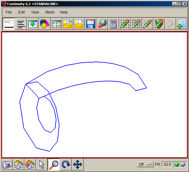
- The mesh should now look similar to the first screenshot
-
Refine mesh circumferentially into four elements
-
-
Enter 4 for xi1, 1 for xi2, and 1 for xi3 under New Element per old element in
-
Select the Local coordinates radio button under New nodal derivatives with respect to:
-
Click OK to submit
-
Change basis functions to cubic Hermite and render mesh
-
-
Select Cubic-Cubic-Cubic under Coordinate 1, Coordinate 2, and Coordinate 3
- All derivatives for all three coordinates should now be enabled
-
Click OK to submit Node Form
-
-
-
If the Dimensions Form appears, simply click Apply Marked Recommendations and then OK
-
-
-
Click lines radio button
-
Click Render to display mesh surface
-
-
-
Click on elements lines2 in the list on the left
-
Click on the Colors tab
-
Change the R,G,B color field to 1.0, 0.0, 0.0 to change the color to the brightest red and hit Enter
-
Click on elements lines1 in the list on the left
-
Check and uncheck the Visibility checkbox a couple times to compare the two different renderings
-
Close the window by clicking the X button
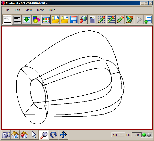
- The mesh should now look similar to the second screenshot
-
Convert coordinates to rectangular Cartesian
-
Mesh→Convert nodes to Cartesian…
-
Leave the update nodes and update coordinates checkboxes checked
-
Click OK
-
-
-
Select the Save, reset, and reload radio button on the bottom
-
Click OK
-
-
-
Click lines radio button
-
Click Render to display mesh surface
-
-
-
Click on elements lines3 in the list on the left
-
Click on the Colors tab
-
Change the R,G,B color field to 0,0,0 to change the color to black and hit Enter
-
Click on elements lines2 in the list on the left
-
Check and uncheck the Visibility checkbox a couple times to compare the two different renderings
-
Close the window by clicking the X button
- The mesh should now look similar to the third screenshot
-
Pre-built model
This cont6 file contains all data and parameters for this problem: mesh7.cont6 (As this is the final model, rendering elements will produce the mesh like the last screenshot)


