Contents
Description
- This example explains Continuity’s convention for interpreting element definitions and then guides the user through a simple exercise to check understanding.
-
The cont6 file contains all data and parameters for this problem.3delem.cont6
Understanding the Continuity Element Definition Convention
-
An element definition tells Continuity how to connect nodes to one another to form elements
-
The element definition is entered into the Elements Form as global node numbers separated by commas
-
A 1D element consists of 2 nodes, so an example of a 1D element definition is: 11,14
-
A 2D element consists of 4 nodes, so an example of a 2D element definition is: 11,14,18,19
-
A 3D element consists of 8 nodes, so an example of a 3D element definition is: 11,14,18,19,21,23,27,29
-
-
The order in which the global node numbers are listed determines how nodes are connected
-
The significance of this order is explained by the convention below, which is specific to Continuity and has no particular meaning outside of it.

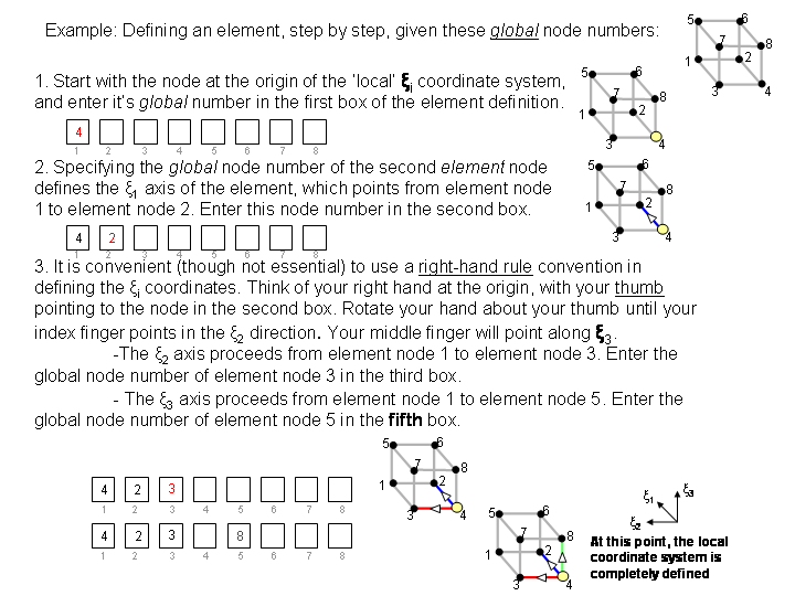
- Study the following example:

Try it for yourself
-
Now that you’ve seen a few examples, try it for yourself in Continuity. A set of eight nodes has already been set up for you with GLOBAL element numbering that looks like this:

- Follow the step-by-step instructions below to load the nodes into Continuity, then try your hand at defining an element
Start Continuity
- Launch the Continuity 6.3 Client
-
On the About Continuity 6.3 startup screen
-
check the Mesh module box under Use Modules:
-
Create Mesh
-
-
Select rectangular cartesian in the Global Coordinates: pop-up menu
-
Click OK to submit Coordinate Form
-
-
-
Choose Lagrange Basis Function→3D→Linear-Linear-Linear with 3 integration/collocation points for Xi 1, Xi 2, and Xi 3
-
Click Add
-
Click OK to submit Basis Form
-
-
-
Click Import/Export/Graph button to open Continuity Table Manager
-
Continuity Table Manager→File→Open…
-
Select tab-delimited nodes file attachment:nodes.xls
-
-
-
Select Linear-Linear-Linear Lagrange 3*3*3 under Coordinate 1, Coordinate 2, and Coordinate 3
-
Click OK to submit Node Form
-
-
-
At this point, follow the step-by-step example at the top of this page for defining an element, BUT note that the global element numbering is different.
- Note that for step 1, you may choose ANY node to be your element origin
- Also note that for step 2, you may choose ANY of the nodes connected to your element origin to define Xi 1
-
Click OK to submit Element Form
-
Render the Result
-
-
Click the lines radio button
-
Click Render to display mesh lines
-
- The rendered element should look something like this (after zooming and rotating appropriately):

- If the element lines look jumbled or wrong, you’ve made a mistake in your ordering. Re-open the elements form and try it again.
-
Once you’ve clicked OK in the elements form, you’ll have to repeat the steps under Render Results to see the change.
-